


About 800 years ago, a French theologian wrote the sentence “Mille viae ducunt homines per saecula Romam”, which was the origin of the saying “All Roads Lead To Rome”. When it comes to software development, this saying holds very true. There are literally endless ways to implement a software application.
In a previous blog, process analysis was positioned as a way to determine the scope and functional goals for application development in the Software Factory. This provides the project with specific goals, modules and required functionality. A good base for an estimate. To keep the analogy going; We decided we will go to Rome by car, though Germany and Switzerland. The trip shouldn’t take more than 2 days.
However, there is still a lot of leeway. Do we only take the highways or the scenic route? Take the ferry along the road or toll roads? The functional goals can still be realised in many ways. To provide guidelines for developers on which exact roads to take, we’ve added the option to create design specifications to the Software Factory.
Design specifications
Creating design specifications is an optional step in the development process, and is positioned inbetween the process analysis phase and the modeling/programming phase of the project. The requirements from the process analysis are input for the design specifications. The design specifications are used to create the model, but also the supplementing logic and corresponding testcases.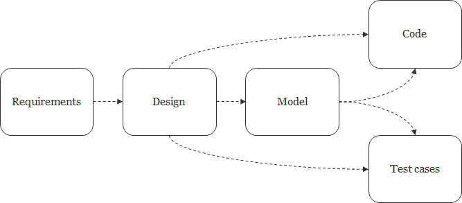
Consider the following functional requirement:
“The application will allow the user to assign multiple employees to a project.”
The obvious solution to implement this is a link table between employee and project. But the requirement is not clear on the exact details of the implementation:
- The users can assign employees to a project by adding records to this link table. A process flow can be introduced to support adding records to the link table.
- There’s also the option of creating a view that shows all employees with a checkbox where the employee is assigned to the current project. An instead-of-update trigger will create or remove records from the link table.
- Alternatively, two views be provided with assigned and unassigned employees with two tasks be provided to assign and remove employees from a project. In this case, the tasks are responsible for adding and removing records from the link table.
Anyone who has enough knowledge to determine the right technical solutions can maintain the design specifications. For the sake of argument, this role will be referred to as the lead developer.
Drafting the design specifications
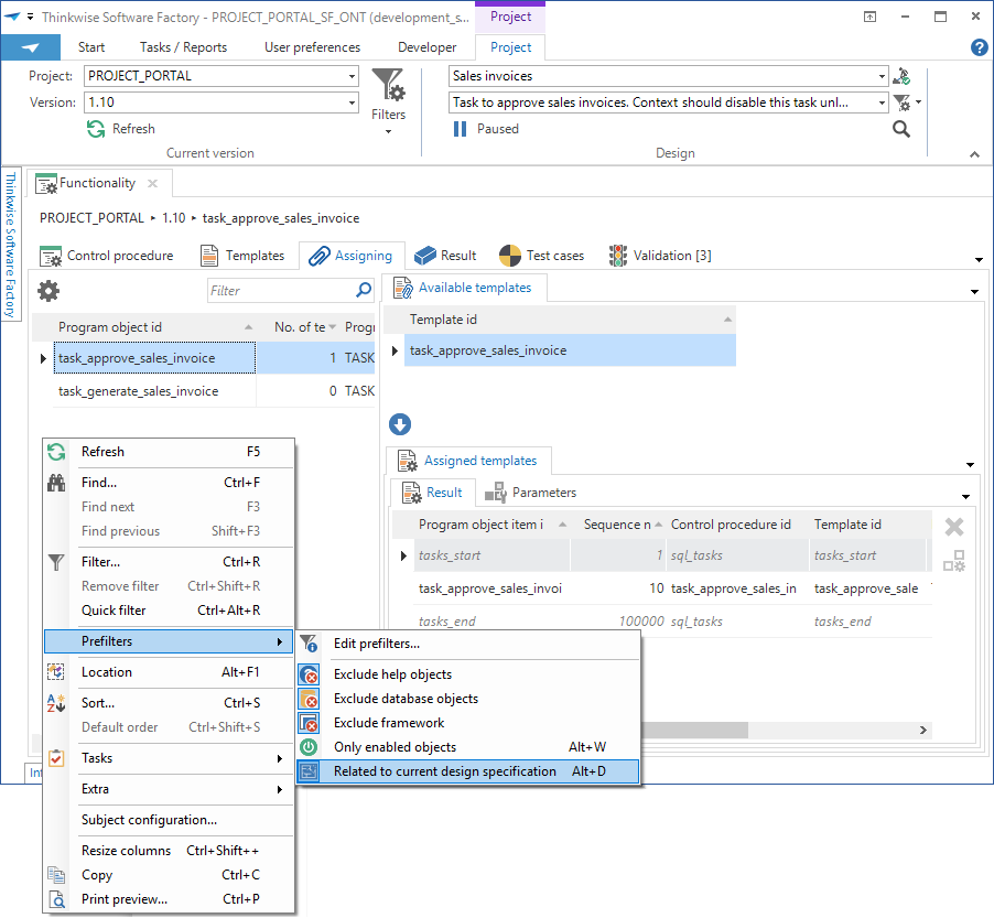
Design can be found in the menu, in the same menu group as the Process analysis. A design specification consists of multiple paragraphs. The lead developer will mark the modelers in which a paragraph of a design specification must be implemented. This can be a single modeler or multiple modelers, depending on the paragraph.On the left you can see an example of a design specification, with a specific paragraph highlighted. This paragraph is a good example to be implemented as a part of the data model.
Traceability from the requirements all the way down to the model can only happen through design specifications. To create traceability, the lead developer can link a design specifications to requirements. This implies that the requirement is (partially) fulfilled by implementing this design. Multiple design specifications can be linked to the same requirement. Cubes are available to detect requirements which have not yet been linked to any design specifications.
It is only possible to link the design specification to functional and non-functional requirements. It is not possible to link a design specification to a user- or business requirement. These types of requirements should not describe any functional aspects of the application.
Just like requirements, design specifications can be divided in modules. When a design specification is part of a module, only requirements of this module will show by default when linking the design specification to requirements.
When the design specification is ready, the design specification can be marked as ‘ready to be implemented’. A specific developer can be assigned to the design specification. If not, any developer will see the new specification.
The progress of implementation is tracked per paragraph, per modeler. An overview is available to see the current status of the design specification. There is a similar overview for entire modules.

Using the design specifications
The specifications show up in the ribbon, where requirements used to be in previous versions. This part of the ribbon is set to paused by default to prevent ‘accidental traceability’.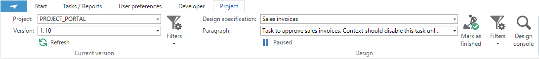
Since the ribbon can only display a limited amount of information, a console button is available to show the design specifications in a seperate pop-up. This pop-up will not block the user interface and is intended to be placed on a separate screen. The active design specification or paragraph is synchronize with the ribbon. Grayed out paragraphs are not marked to be implemented in the current modeler, or are already marked as finished.

Modifications to the model done by the developer will be linked to the selected paragraph. This facilitates the final step of the traceability from requirements down to the model. When the developer has implemented the paragraph, the paragraph can be marked as finished. Marking a paragraph as finished only applies for the current modeler. A paragraph can require implementations in several modelers.
When modifications are done while a paragraph is selected but the paragraph is grayed out, the paragraph will automatically spring open for the current modeler and can be marked as finished again.
What about application logic?
Application logic specifications no longer exist. The application logic specifications have been replaced by design specifications for functionality, messages and test cases. Existing application logic will be upgraded to design specifications as part of the upgrade to G9.8.The ability to show application logic specifications in the product has been removed. We are still in the process of examining alternatives based on design specifications.
Application logic had the nifty feature of generating static assigments for templates. This feature has been replaced with a prefilter when assigning templates This prefilter limits the list of program objects to program objects which have been affected by the current design specification. For instance, when the tasks Generate_sales_invoice and Approve_sales_invoice have been added for a certain design specification and the developer is assigning a template for the same design specification, the developer can use this prefilter and the list of program objects will be limited to program objects relating to those two tasks.
Starting with design specifications
Design specifications can be used in new projects to convey implementation details to the development team. But quite a few Software Factory instances will be upgraded to the G9.8 and already have a finished or partially finished model. For project maintenance, the design specifications can be used to describe modifications to the existing model.Good luck! And as always, feedback is appreciated.
(TLDR; Design specifications are created as free-text instructions on how to implement the application. Design specifications can be based on the requirements. Developers can use the design specifications as a to-do list for the entire model.)